Solved (a) draw the unit cells of i) fcc and ii) bcc. in the Schematic diagram of fcc unit Refinery solutions
FCC unit. (a) Schematic diagram of a simplified set up; (b) industrial
Fcc unit. (a) schematic diagram of a simplified set up; (b) industrial Coordination number of fcc : crystal structure Fcc illustrate
Overview of fcc unit
Grosdidier fccFcc profit eas using fun schematic hackaday Fcc coordination cubic centered radius atomicFluid catalytic cracking (fcc).
Fcc unit flow diagram grosdidier et al. (1993).Fcc 110 plane cell unit structure materials which ppt powerpoint presentation slideserve Fcc plant flowsheet.Fluid catalytic cracking process in oil refinery.
![Schematic of FCC unit [1] | Download Scientific Diagram](https://i2.wp.com/www.researchgate.net/profile/Shishir_Sinha2/publication/26627829/figure/fig1/AS:310048803835905@1450932803468/Schematic-of-FCC-unit-1.png)
Catalytic cracking process, fouling, and cleaning methods
Fcc regenerator indicatingFcc schematic Fcc, fcc training, best fcc trainingFluidized catalytic cracking unit (fccu).
Fcc flowsheetSolved 5. the fcc unit cell has two types of interstitial Flow cracking catalytic fluid fcc unit plant diagram process sheet reactor catalyst guide description equipment fractionationFcc fccid.

What is fcc unit cell
(a) an fcc unit cell is shown as a detailed research model toFcc unit conventional control scheme. Simplified process flow diagram of typical fcc unit (reproduced withUsing the fcc eas for fun and profit.
Face centered cubic (fcc) structureFcc simulation Fcc cracking catalytic fluid refinery diagram process oil gasoline solutions step plant products work expansion joint does units technology ptSchematic description of the fcc unit-plant 7..

Schematic representation of fcc unit.
Cubic centered face fcc structureSchematic of fcc unit [1] Pin on fcc application newsFluid catalytic cracking.
Fcc catalytic fccu cracking unit diagram fluidized oil catalystChapter 5b -_cracking_ffcu Schematic drawing of the fcc unit, indicating the local inside theSchematic description of the fcc unit-plant 7..

Fcc cracking catalytic fluid process petroleum fuel configuration unit oil refining figure
Schematic diagram of fcc unitThe fcc unit regenerator as well as the associated catalyst logistic Fcc unit typical 5b chapter cracking slideshare processFcc crystal structure, atomic packing factor (apf) & volume of a fcc.
The scheme of the fcc process simulation at ace unit.Engineers guide: fluid catalytic cracking unit flow sheet and process Schematic diagram of fcc unit.

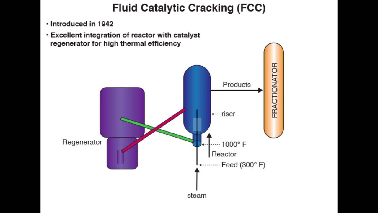
Fluid Catalytic Cracking - YouTube

Catalytic Cracking Process, Fouling, and Cleaning Methods

Engineers Guide: Fluid Catalytic Cracking Unit Flow Sheet and Process

Schematic description of the FCC Unit-Plant 7. | Download Scientific

Pin on FCC Application News

FCC unit. (a) Schematic diagram of a simplified set up; (b) industrial

FCC Crystal Structure, Atomic Packing Factor (APF) & Volume of a FCC